


Parts from plates
Phase I - Preparing the parts made from metal plates
Fold, pound, and cut the body plates
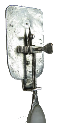
The body plates of the 248x silver microscope at the bottom of this page are a little less than 90% pure silver. They measure ?? x ?? mm x ?? mm.
We do not know where the silver came from or in what form Leeuwenhoek acquired it. He wrote to the members of the Royal Society in Letter 140 on August 2, 1701 (AB 228) that he extracted his own silver from ore.
... 26 magnifying glasses, all of which have been ground by me and are in a silver setting and mounted with silver, most of them with the silver I extracted from mineral and separated from the gold with which it was contaminated
Or he could have purchased a plate or hunk of silver from one of the silversmiths in town.
To make sure the holes would line up, Leeuwenhoek hammered out a flat piece of silver a little larger than the palm of his hand. He folded it over and pounded it some more with his hammer. The side view at the bottom of this page gives a clear picture of how thin each of the two plates had to be, around a millimeter each, in order for the two plates to be thinner than the lens.
He used a chisel to roughly shape the two body plates as a matching pair. By tapering one end a little, he designated at which end the braking screw would secure the bracket to the body plates.
 Drill matching round holes for the lens, the rivets, and the braking screw
To temporarily keep the plates together, Leeuwenhoek clamped them to a tabletop. He drilled matching round holes in the four corners and midway between them along the sides. The close-up on the right (click to enlarge) shows the rivet already in the hole. Perhaps the plates were thin enough that he could use a punch.
While he had the plates clamped, he drilled the hole for the braking screw in the middle but toward the tapered end.
The drill bit for the rivets was the same size as rivets. However, the hole for the braking screw would be threaded. If he did not know what screw he would use yet, this step could have been done in the next phase when he used a tap to make threads in this hole.
To complete this pattern, Leeuwenhoek punched the hole for the lens, what we began calling an aperture a hundred years ago. The idea with the rivet holes was to keep the plates touching each other securely. For the lens hole, however, he had to leave room between the plates for the tiny bead of ground glass. After the body plates were securely riveted, they had to hold the lens tightly enough that it couldn't shift its position. On the other hand, if the plates held it too tightly, it might crack. It would be especially vulnerable while he pounded the rivets in.
 To make the space for the lens, he separated the plates and placed each on a softer material, perhaps leather. With a tiny punch, he tapped what you see in the image on the right (click to enlarge) as a raised circle with the lens hole in the center. This close-up of the 248x silver microscope pictured in three views below also came from the Boerhaave Museum's authentication team.
Did Leeuwenhoek have a lens to tailor this space to?
A larger hole would let in more light. A smaller hole would decrease spherical abberation, a 19th century phrase but a phenomenon that 17th century microscopists knew well.
Did he use wax, which was Hooke's suggestion in Micrographia for a microscope with a single plate?
The challenge of getting enough wax around the lens to secure it yet not interfere with viewing may well have led Leeuwenhoek to the matching plates solution. However, a little wax applied behind the lens holes could have been very helpful. No one has separated any of the microscopes' plates to find out. Nor is anyone likely to but perhaps 3D imaging techniques could answer the wax question.
Cut and bend the L-bracket; drill holes for two screws
The metal in the L-bracket doesn't seem to have been measured separately, either for size or purity, so we don't know whether Leeuwenhoek chiseled it out of trim from the plates or made it as part of a batch of brackets. It was much longer than it was wide, barely wider than the screws.
 The side view below shows that the L-bracket is about as thick as both plates together. The eye-side view shows that the bracket was wider at one end to accomodate the braking screw and its nut. Assuming that the braking and positioning screws were made at the same time with the same die, it is interesting that Leeuwenhoek felt the braking screw needed more support.
Leeuwenhoek drilled a hole in either end of the silver strip, one hole for the braking screw and one for the main positioning screw. He wrote to the Royal Society in Letter 66 of January 12, 1689 (AB 113) about a similar technique when constructing his eel viewers:
I then worked the said piece of brass in such a way on the dotted parts of the line PR., that it there made a right angle.
"Worked ... in such a way" suggests that be bent the metal strip, perhaps over an edge, into an L-shape closer to one hole, which was thus the hole for the positioning screw.
File the plates and bracket
A chisel is a crude tool. This microscope shows many scratch marks made by files, as in the close-up on the right (click to enlarge). The close-up also shows that Leeuwenhoek filed the edges of the body plates until they were uniformly smooth. Did he use a clamp or vise to secure the tiny piece of silver? Was it better to holding the silver in one hand and file with the other?
 |
 |
 |


